


VANCOUVER, British Columbia, June 30, 2026 (GLOBE NEWSWIRE) — Li-FT Power Ltd. (“LIFT” or the “Company”) (TSXV: LIFT) (ASX:LFT) (OTCQX: LIFFF) (Frankfurt: WS0) is pleased to report results from the 2026 winter and 2025 summer programs completed at the Yellowknife Lithium Project (“YLP”), located outside the city of Yellowknife, Northwest Territories (Figure 1).
This news release provides results from 20 holes drilled on the YLP, for a total of 5,324 m. Seventeen of these holes (4,778 m) were drilled as part of the 2026 winter program and three (546 m) were drilled as part of the 2025 summer work program.
Highlights from the results reported in this news release include:
- YLP-0304: 21 m at 1.09% Li2O (Fi Main)
Including 13 m at 1.38% Li2O - YLP-0306: 18 m at 1.41% Li2O (Ki)
- YLP-0312: 26 m at 1.29% Li2O (BIG East)
Including 17 m at 1.65% Li2O - YLP-0315: 22 m at 1.09% Li2O (BIG East)
- YLP-0320: 17 m at 1.32% Li2O (BIG East)
Figure 1 – Location of LIFT’s Yellowknife Lithium Project (YLP) in the NWT.
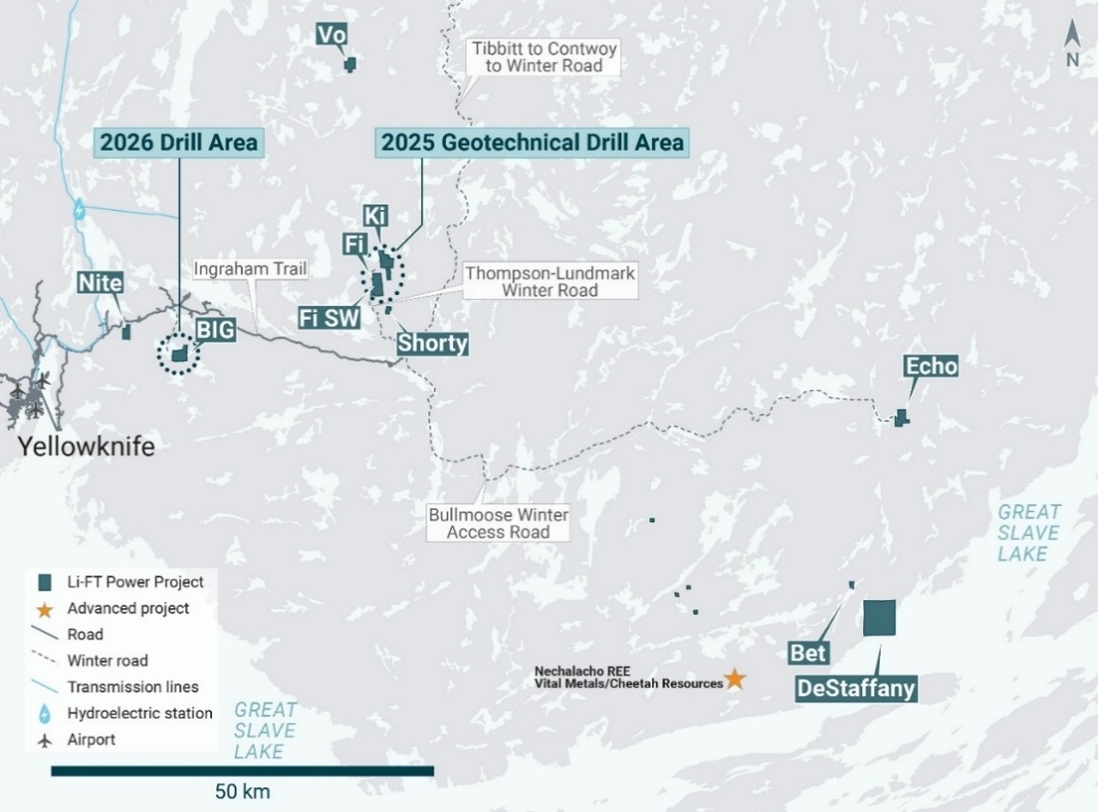

Figure 2 – Location of LIFT’s BIG, Fi Main (Fi), Fi SW, and Ki pegmatites within the YLP.
The seventeen 2026 holes were all drilled in the BIG area of the YLP (Figure 2), marking the first drill campaign at BIG since publication of the inferred mineral resource released to the TSXV in October 2024 and ASX on 22 May 2026.1
The three holes from the 2025 program were drilled on the Fi Main, Fi SW, and Ki pegmatites (Figure 2) and underwent geotechnical strength testing before geochemical analysis.
Discussion of Results
BIG pegmatite
The BIG area includes the BIG East, West, and North pegmatites, with BIG North representing either a separate complex from BIG East or its fault-offset northern extension. Sixteen of the 2026 holes were drilled on the BIG East pegmatite, and one hole was drilled at BIG North (Figure 3).
The BIG East pegmatite complex comprises a north-northeast trending corridor of parallel-trending dykes that is exposed for at least 1.8 km of strike length, ranges from 10-100 m wide, and dips approximately 55°-75° to the west. Spodumene-bearing pegmatite may occur either as a single dyke 20-35 m wide, or as two to four dykes of similar cumulative thickness within corridors up to 65 m wide. The holes drilled as part of the 2026 winter program extend along 1,000 m of strike length and reach depths of 50 to 300 m below surface.
The BIG North pegmatite comprises a north-northeast trending dyke swarm exposed over at least 350 m of strike length, ranging from 10-35 m in width, and dipping approximately 70° west.
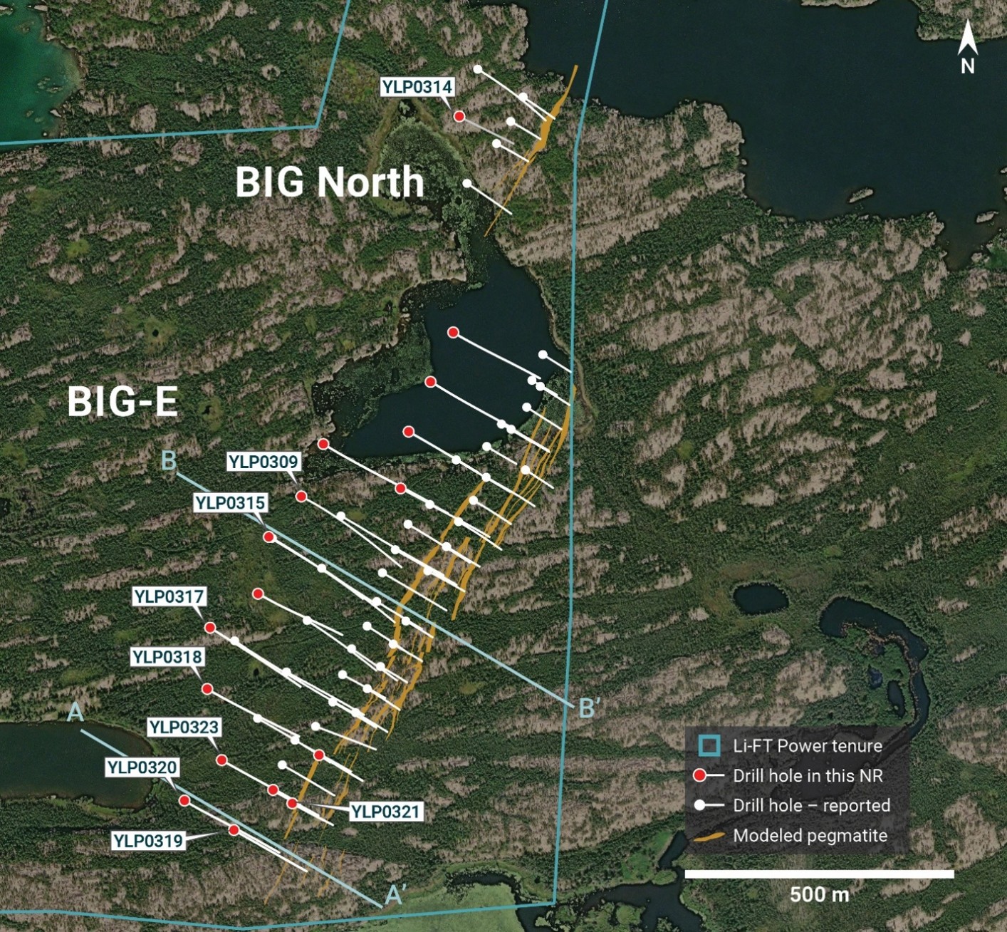

Figure 3 – Plan map showing BIG tenure boundary, pegmatite dykes, 2023-2024 drill holes2, and the 2026 winter drill holes.
Collar geographic locations and assay highlights are provided in Appendix 1.
YLP-0319 and 0320 are the most southerly holes drilled on the BIG East complex, testing 100 and 200 m below surface respectively. YLP-0320 returned the better grades, intersecting a 20-m-wide pegmatite dyke that assayed 1.32% Li2O over 17 m (Appendix 1, Figure 4), leaving the BIG East mineralized system open to the south and at depth.
YLP-0319 was drilled 100 m up-dip of YLP-0320 and cut through a 59-m-wide corridor, hosting five pegmatite dykes with cumulative width of 19 m. The thickest of these dykes returned a wall-to-wall composite of 1.22% Li2O over 11 m (Appendix 1, Figure 4).
Holes YLP-0321, 0322, and 0323 were drilled on a section 100 m north of YLP-0319 and 0320. At around 50 m below the surface, YLP-0321 drilled through a 100-m-wide corridor that hosts eight pegmatite dykes with a cumulative width of 28 m. Four of these dykes are spodumene-bearing, with the better composites including 1.24% Li2O over 5 m and 1.08% Li2O over 5 m (Appendix 1).
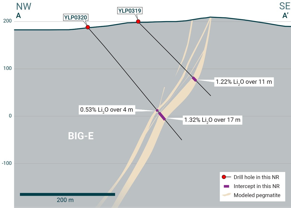

Figure 4 – Section A-A’ (refer to Figure 3) looking northeast and showing the BIG East pegmatite as well as results from 2026 drilling.
YLP-0322 was designed to test the same corridor approximately 50 m downdip of YLP-0321 and intersected seven dykes totalling 33 m of pegmatite across a drilled width of 75 m. Four of these dykes are spodumene-bearing, returning intersections of 1.15% Li2O over 9 m, 0.97% Li2O over 10 m, 0.57% Li2O over 5 m, and 0.53% Li2O over 2 m (Appendix 1).
YLP-0323 was drilled to test a further 100 m downdip of YLP-0322, intersecting a 54-m-wide corridor with four dykes that sum to 33 m of pegmatite and returning composites of 0.82% Li2O over 6 m and 1.30% Li2O over 1 m (Appendix 1).
YLP-0318 and 0324 were drilled on a section 100 m north of the section with YLP-0321 to 0323. Hole YLP-0324 returned the better grades and was designed to test 50 m below surface and 50 m up-dip of YLP-00683, which was drilled in 2023. Drilling intersected three dykes totalling 16 m of pegmatite over a drill width of 49 m, with the widest returning 1.04% Li2O over 11 m (Appendix 1).
YLP-0318 was drilled 250 m downdip of YLP-0324 and 100 m downdip of 2023 drill hole YLP-01013, intersecting a 92-m-wide corridor with nine dykes totalling 37 m of pegmatite. Spodumene contents are generally low, with the best intersections returning 0.65% Li2O over 3 m and 0.67% Li2O over 2 m (Appendix 1).
YLP-0317 was drilled a further 100 m north of the section with YLP-0318 and 0324, to test the BIG East corridor 300 m below the surface and 125 m downdip of YLP-0115, which was drilled by LIFT in 2023. The drill hole intersected a 32-m-wide pegmatite dyke with negligible spodumene mineralization.
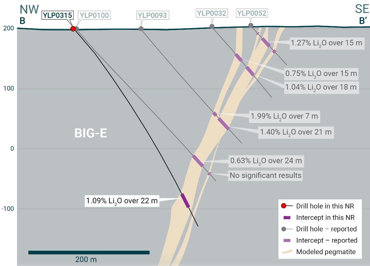

Figure 5 – Section B-B’ (refer to Figure 3) looking northeast and showing the BIG East pegmatite.4
Holes YLP-0316 was collared 100 m north of YLP-0317 to test the BIG East complex at approximately 300 m below surface and 100 m downdip of YLP-0117, drilled by LIFT in 2023.4 New drilling intersected a 22-m-wide pegmatite dyke at the expected depth but with negligible spodumene.
YLP-0315 was collared on a section 100 m north of YLP-0316, near the center of the complex, to test the pegmatite corridor at 200 m below surface and LIFT’s 2023 holes YLP-0093 and YLP-0100.4 New drilling intersected a 24-m-wide pegmatite dyke that returned 1.09% Li2O over 22 m (Appendix 1, Figure 5).
YLP-0309 was collared 100 m further north to test the central part of the BIG East corridor at 200 m below surface, as well as 50 m downdip of hole YLP-0077, drilled by LIFT in 20234. New drilling intersected a 27-m-wide pegmatite dyke with an interval of 10 m averaging 0.66% Li2O, including 1.13% Li2O over 4 m (Appendix 1).
YLP-0312 and 0308 were drilled on a section 100 m north of YLP-0309, to test the BIG East corridor at 175 m and 275 m below surface, respectively. YLP-0312 tested 100 m down-dip of YLP-0058, drilled by LIFT in 2023,4 and intersected a 26-m-wide pegmatite dyke that returned a wall-to-wall composite of 1.29% Li2O over 26 m, including 17 metres averaging 1.65% Li2O (Appendix 1, Figure 6).
YLP-0308 was drilled an additional 100 m downdip of YLP-0312, intersecting four pegmatite dykes totalling 45 m within a drilled width of 57 m, but with negligible spodumene.
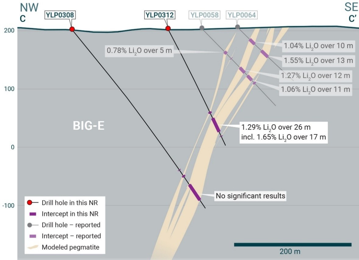

Figure 6 – Section C-C’ (refer to Figure 3) looking northeast and showing the BIG East pegmatite.5
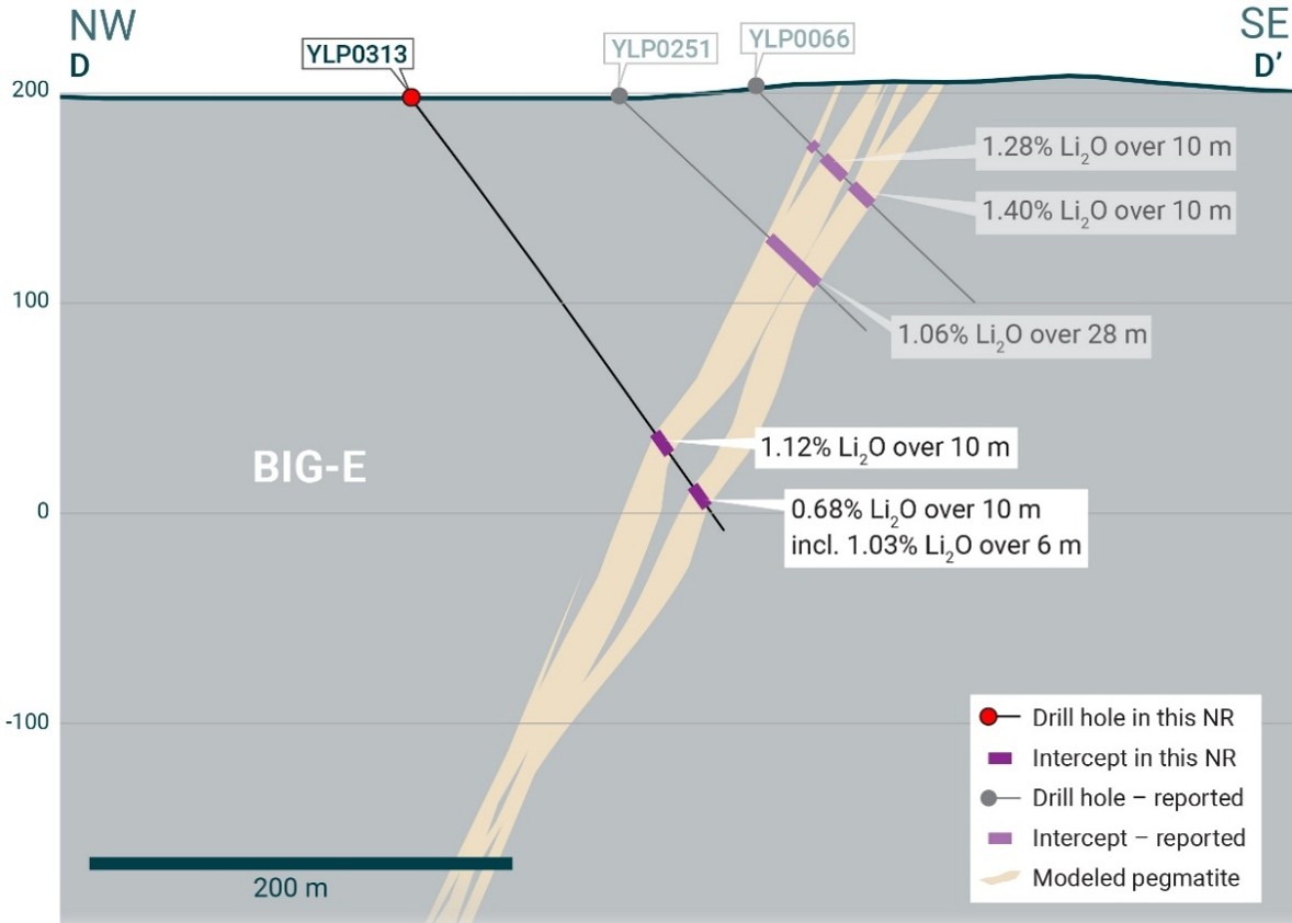

Figure 7 – Section D-D’ (refer to Figure 3) looking northeast and showing the BIG East pegmatite.5
YLP-0313 was collared 100 m north of YLP-0312, to test the BIG East complex at 175 m below surface and 100 m downdip of YLP-0251, drilled by LIFT in 2024.6 New drilling intersected 12- and 10-m-wide dykes spaced 22 m apart, with the upper one returning 1.12% Li2O over 10 m and the lower one 0.68% Li2O over 10 m, including 6 m of 1.03% Li2O (Appendix 1, Figure 7). Mineralization on this section remains open at depth.
YLP-0310 and 0311 were drilled at the north end of the BIG East pegmatite to, respectively, test 100 m downdip of LIFT’s 2024 drill holes YLP-0271 and YLP-0267.6 Both new drill holes intersected 20- to 30-m-wide pegmatite at their expected depths, with negligible spodumene.
YLP-0314 was the only hole drilled at BIG North in the winter 2026 program targeting 100 m downdip of 2023 drill hole YLP-0129.6 No pegmatite was intersected.
Fi Main Pegmatite
The Fi Main pegmatite complex crops out over at least 1.5 km of strike length within a north-south striking corridor that dips between 70°-85° to the west. The dyke can be split into several structural domains, each ~400 to 500 in strike length, that include stretches comprising just a single 25-30 m thick dyke or two or more dykes of similar cumulative thickness within a broader corridor that is up to 150 m wide.
YLP-0304 was drilled in the southern part of Fi Main (Figure 8), where it split into two thick dykes, for the purpose of collecting whole-core material for rock mechanics testing. Assays from the upper dyke returned 1.09% Li2O over 21 m, including 1.38% Li2O over 13 m, whereas the lower dyke assayed 0.56% Li2O over 29 m with a 9-m subinterval averaging 1.03% Li2O (Appendix 1, Figure 9).
Fi SW Pegmatite
The Fi Southwest (SW) pegmatite complex is exposed over at least 1.1 km on surface and occurs within a broader corridor that is 50-100 m wide and dips between 60°-80° to the east. The complex is cored by a 20-40 m wide dyke that is continuous for at least 800 m along strike, with numerous sub-parallel subsidiary dykes between 1-5 m in width. At its northern and southern ends, the main dyke splays out into a broader corridor with more dykes that have narrower widths.
YLP-0305 was drilled near the northern end of the Fi SW pegmatite (Figure 10) to collect whole-core material for geotechnical testing. Drilling targeted the dyke 150 m below surface and offsetting 25 m down-dip from YLP-0047, which was drilled by LIFT in 2023.6 New drilling intersected a 25-m-wide pegmatite that returned a composite of 0.50% Li2O over 21 m, including 1.10% Li2O over 8 m (Appendix 1, Figure 11).
Ki Pegmatite
The Ki pegmatite complex comprises a north-northwest trending corridor of dykes that extends for at least 1.3 km on surface and dips steeply to the southwest. The southern part of the corridor consists mostly of one large dyke and several narrower flanking dykes that sum to a pegmatite width of approximately 25 m. The northern end of the complex consists of two relatively thick dykes that are located 50-150 m apart.
YLP-0306 was drilled in the centre of the dyke complex (Figure 12) to collect whole rock material for geotechnical testing. The hole targeted the dyke 100 m below surface, offsetting 25 m downdip from 2023 drill hole YLP-104.6 New drilling intersected a 23 m wide pegmatite dyke that returned a composite of 1.41% Li2O over 18 m (Appendix 1, Figure 13).
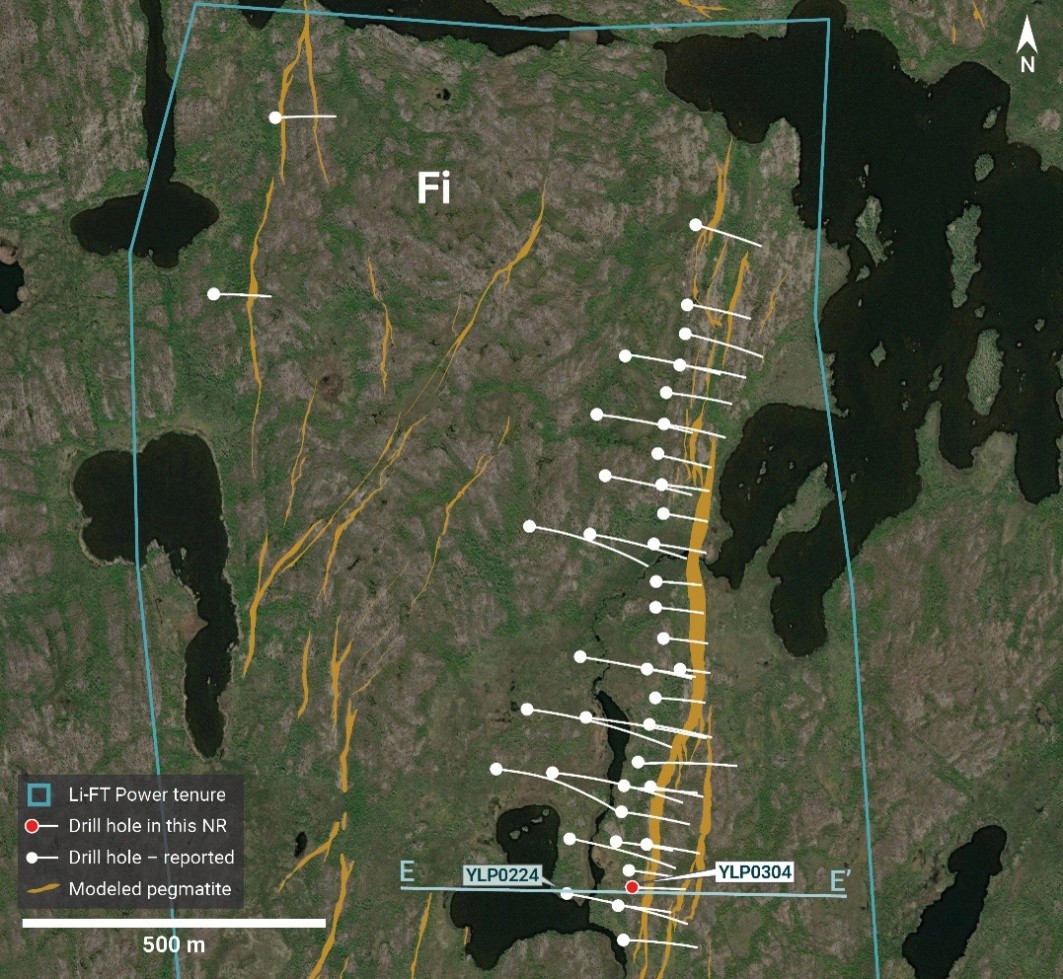

Figure 8 – Plan map showing Fi tenure boundary, pegmatite dykes, 2023-20247 drill holes, and the 2025 geotechnical drill hole.
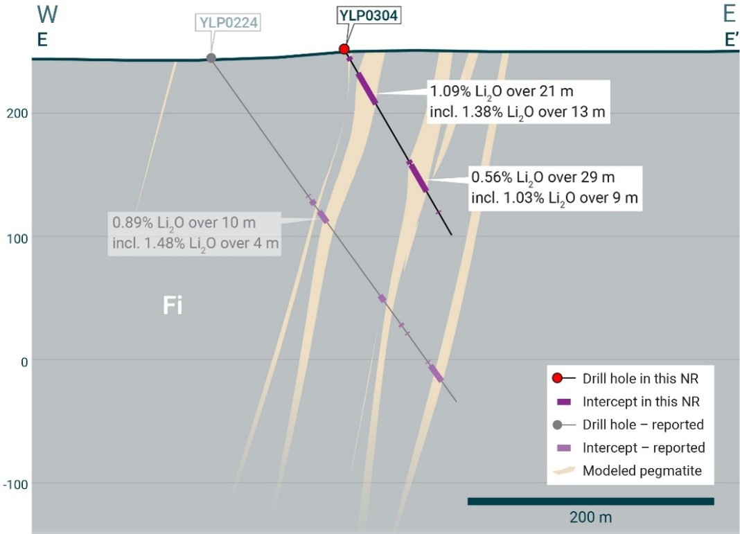
Figure 9 – Section E-E’ (refer to Figure 8) looking north and showing the Fi Main pegmatite.7
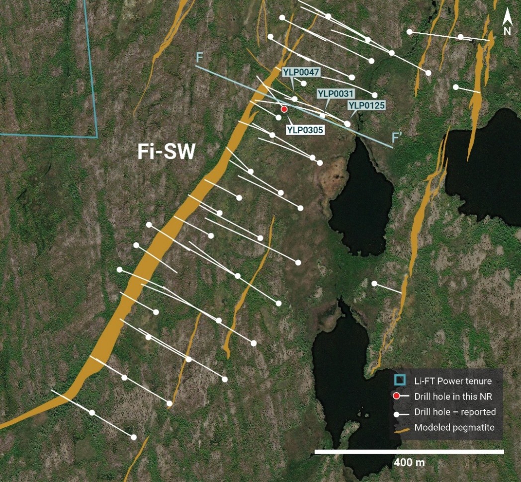
Figure 10 – Plan map showing Fi tenure boundary, pegmatite dykes, 2023-2024 drill holes8, and the 2025 geotechnical drill hole.
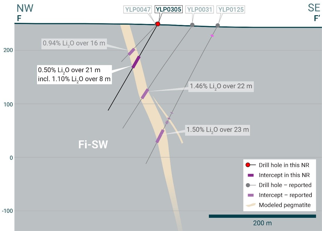

Figure 11 – Section F-F’ (refer to Figure 10) looking northeast and showing the Fi SW pegmatite.8
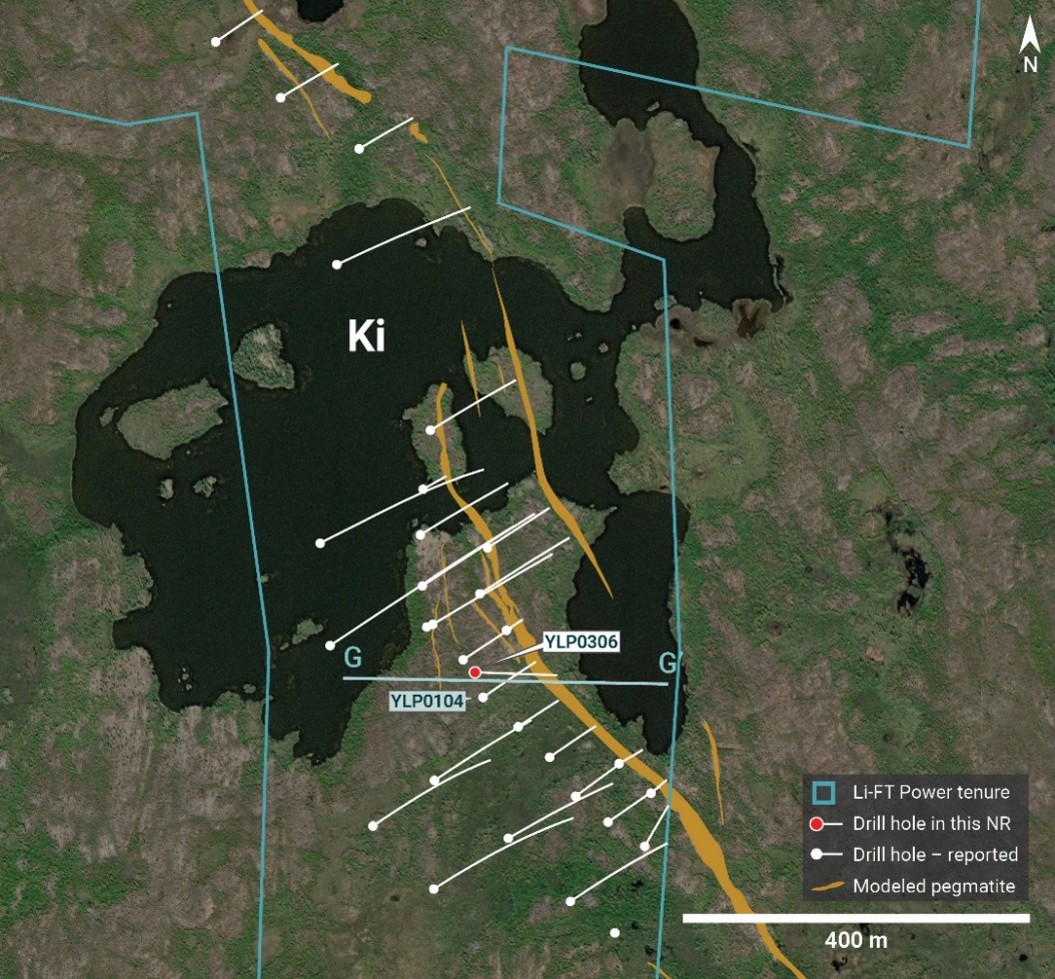

Figure 12 – Plan map showing Ki tenure boundary, pegmatite dykes, 2023-2024 drill holes9, and the 2025 geotechnical drill hole.
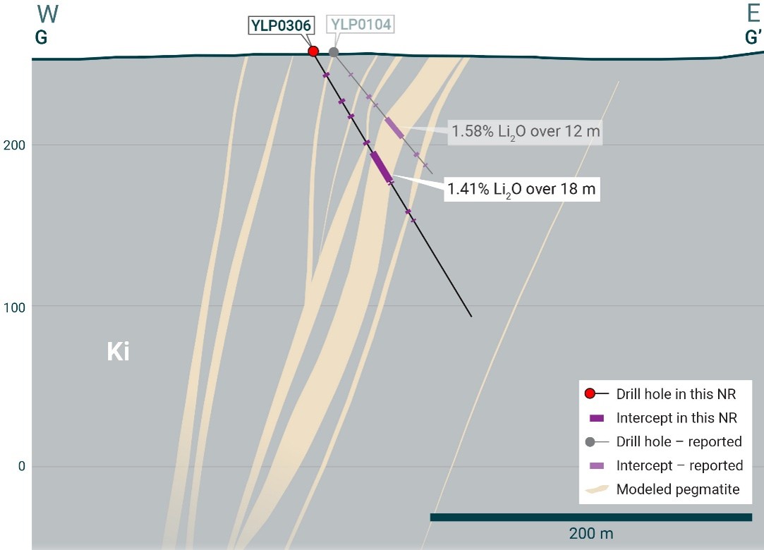

Figure 13 – Section G-G’ (refer to Figure 12) looking north and showing the Ki pegmatite.9
General Statements
All winter 2026 holes described in this news release were drilled broadly perpendicular to the dyke orientation so that the true thickness of reported intercepts will range somewhere between 65-100% of the drilled widths.
The summer 2025 geotechnical holes were drilled slightly oblique to resource definition holes to capture more material for geotechnical testing, so that true widths are approximately 50-90% of drilled widths.
A collar header table for the drill holes in this news release is provided in Appendix 1.
Visual core logging, mineralogical studies, and metallurgical work confirm that the predominant host mineral for lithium is spodumene.
QAQC
All drill core samples were collected under the supervision of LIFT employees and contractors. Drill core was transported from the drill platform to the core processing facility where it was logged, photographed, and split by diamond saw prior to being sampled. Samples were then bagged, and blanks and certified reference materials were inserted at regular intervals. Field duplicates consisting of quarter-cut core samples were also included in the sample runs. Groups of samples were placed in large bags, sealed with numbered tags in order to maintain a chain-of-custody, and transported from LIFT’s core logging facility to ALS Labs (“ALS”) laboratory in Yellowknife, Northwest Territories.
Sample preparation and analytical work for this drill program were carried out by ALS. Samples were prepared for analysis according to ALS method CRU31: individual samples were crushed to 70% passing through 2 mm (10 mesh) screen; a 1,000-gram sub-sample was riffle split (SPL-21) and then pulverized (PUL-32) such that 85% passed through 75-micron (200 mesh) screen. A 0.2-gram sub-sample of the pulverized material was then dissolved in a sodium peroxide solution and analysed for lithium according to ALS method ME-ICP82b. Another 0.2-gram sub-sample of the pulverized material was analysed for 53 elements according to ALS method ME-MS89L. All results passed the QA/QC screening at the lab, all inserted standards and blanks returned results that were within acceptable limits.
This release is authorised by the Board of Directors of Li-FT Power Ltd.
| For further information, please contact: | |
| Francis MacDonald | Daniel Gordon |
| Chief Executive Officer | Investor Relations Manager |
| Tel: + 1.604.609.6185 | Tel: +1.604.609.6185 |
| Email: investors@li-ft.com | Email: investors@li-ft.com |
| Website: www.li-ft.com | |
About LIFT
LIFT is focused on developing a portfolio of hard rock lithium assets in Canada, with core development assets in both Quebec and the Northwest Territories. The Company owns the Yellowknife Lithium Project in the Northwest Territories and the Adina Lithium Project in the Eeyou Istchee James Bay region of Quebec. LIFT also holds early-stage exploration properties in both jurisdictions.
Qualified Person
The disclosure in this news release of scientific and technical information regarding LIFT’s mineral properties has been reviewed and approved by Ron Voordouw, Ph.D., P.Geo., Partner, Director Geoscience, Equity Exploration Consultants Ltd., and a consultant to Li-FT Power Ltd. He is a Qualified Person as defined by National Instrument 43-101 Standards of Disclosure for Mineral Projects (NI 43-101) as well as a member in good standing with the Northwest Territories and Nunavut Association of Professional Engineers and Geoscientists (NAPEG) (Geologist Registration number: L5245).
Competent Person’s Statement
Information in this announcement that relates to exploration results is based on and fairly represents information and supporting documentation obtained by LIFT and reviewed and approved by Mr. Ben Eggers, MAIG, P.Geo., Senior Geologist, SGS Canada Inc. – SGS Geological Services, a Competent Person who is a Member of the Australian Institute of Geoscientists. Mr. Eggers has sufficient experience that is relevant to the style of mineralisation and type of deposit under consideration and to the activity which he is undertaking to qualify as a ‘Competent Person’ as defined in the 2012 Edition of the ‘Australasian Code for Reporting of Exploration Results, Mineral Resources and Ore Reserves’ (“JORC Code”). Mr. Eggers is an independent consultant with SGS Canada Inc. – SGS Geological Services and Mr. Eggers consents to the inclusion in this announcement of the matters based on this information in the form and context in which it appears.
Past Exploration Results and Mineral Resource estimates referenced in this announcement were first reported by the Company in accordance with ASX Listing Rules 5.7 and 5.8 in its Prospectus lodged with ASIC on 13 April 2026 and ASX on 22 May 2026 (Prospectus). The Company confirms that it is not aware of any new information or data that materially affects the information included in the Prospectus and that in the case of the Mineral Resource estimates, that all material assumptions and technical parameters underpinning the estimates in the Prospectus continue to apply and have not materially changed. The Company confirms that the form and content in which the Competent Person’s findings are presented here have not been materially modified from the Prospectus.
Cautionary Statement Regarding Forward-Looking Information
Certain statements included in this press release constitute forward-looking information or statements (collectively, “forward-looking statements”), including those identified by the expressions “anticipate”, “believe”, “plan”, “estimate”, “expect”, “intend”, “may”, “should” and similar expressions to the extent they relate to the Company or its management. The forward-looking statements are not historical facts but reflect current expectations regarding future results or events. This press release contains forward looking statements. These forward-looking statements and information reflect management’s current beliefs and are based on assumptions made by and information currently available to the company with respect to the matter described in this new release.
Forward-looking statements involve risks and uncertainties, which are based on current expectations as of the date of this release and subject to known and unknown risks and uncertainties that could cause actual results to differ materially from those expressed or implied by such statements. Additional information about these assumptions and risks and uncertainties is contained under “Risk Factors” in the Company’s latest annual information form filed on April 27, 2026, which is available under the Company’s SEDAR+ profile at www.sedarplus.ca, and in other filings that the Company has made and may make with applicable securities authorities in the future. Forward-looking statements contained herein are made only as to the date of this press release and we undertake no obligation to update or revise any forward-looking statements whether as a result of new information, future events or otherwise, except as required by law. We caution investors not to place considerable reliance on the forward-looking statements contained in this press release.
Neither the TSX Venture Exchange nor its Regulation Services Provider (as that term is defined in the policies of the TSX Venture Exchange) accepts responsibility for the adequacy or accuracy of this news release.
Appendix 1.
Diamond drilling hole details
| Year | Hole number | NAD83zone | Easting | Northing | Elevation (m ASL) | Length (m) | Azimuth | Dip | Interval Type | From (m) | To (m) | Interval (m) | Li2O (%) | Dyke |
| 2025 | YLP0304 | Zone 12N | 371747 | 6941360 | 253.7 | 172 | 92 | 60 | 27 | 48 | 21 | 1.09 | Fi Main | |
| including | 33 | 46 | 13 | 1.38 | ||||||||||
| and | 102 | 131 | 29 | 0.56 | ||||||||||
| including | 116 | 125 | 9 | 1.03 | ||||||||||
| YLP0305 | Zone 12N | 371421.6 | 6940969 | 249.2 | 184 | 320 | 60 | 71 | 92 | 21 | 0.50 | Fi SW | ||
| including | 84 | 92 | 8 | 1.10 | ||||||||||
| YLP0306 | Zone 12N | 373059.2 | 6942796 | 256.2 | 190 | 92 | 60 | 73 | 91 | 18 | 1.41 | Ki | ||
| 2026 | YLP0308 | Zone 12N | 345908.4 | 6933357 | 197.3 | 383 | 121 | 50 | No significant results | BIG East | ||||
| YLP0309 | Zone 12N | 345868.1 | 6933259 | 200.5 | 356 | 118 | 52 | 282 | 292 | 10 | 0.66 | BIG East | ||
| including | 283 | 287 | 4 | 1.13 | ||||||||||
| YLP0310 | Zone 12N | 346107 | 6933472 | 197.1 | 285 | 121 | 50 | No significant results | BIG East | |||||
| YLP0311 | Zone 12N | 346149.8 | 6933563 | 198.0 | 340 | 121 | 52 | No significant results | BIG East | |||||
| YLP0312 | Zone 12N | 346052.1 | 6933275 | 201.4 | 222 | 121 | 62 | 170 | 196 | 26 | 1.29 | BIG East | ||
| including | 177 | 194 | 17 | 1.65 | ||||||||||
| YLP0313 | Zone 12N | 346066.6 | 6933380 | 197.0 | 254 | 121 | 51 | 198 | 208 | 10 | 1.12 | BIG East | ||
| and | 230 | 240 | 10 | 0.68 | ||||||||||
| including | 233 | 239 | 6 | 1.03 | ||||||||||
| YLP0314 | Zone 12N | 346160.7 | 6933963 | 204.1 | 224 | 121 | 57 | No significant results | BIG North | |||||
| YLP0315 | Zone 12N | 345807.7 | 6933184 | 198.0 | 345 | 123 | 46 | 289 | 311 | 22 | 1.09 | BIG East | ||
| YLP0316 | Zone 12N | 345787.9 | 6933080 | 198.0 | 338 | 120 | 55 | No significant results | BIG East | |||||
| YLP0317 | Zone 12N | 345699 | 6933016 | 200.7 | 419 | 120 | 60 | No significant results | BIG East | |||||
| YLP0318 | Zone 12N | 345693.8 | 6932903 | 196.7 | 387 | 121 | 56 | 289 | 292 | 3 | 0.65 | BIG East | ||
| and | 316 | 318 | 2 | 0.67 | ||||||||||
| YLP0319 | Zone 12N | 345743.1 | 6932642 | 196.2 | 218 | 121 | 45 | 163 | 174 | 11 | 1.22 | BIG East | ||
| YLP0320 | Zone 12N | 345651.5 | 6932696 | 186.8 | 309 | 121 | 50 | 226 | 230 | 4 | 0.53 | BIG East | ||
| and | 237 | 254 | 17 | 1.32 | ||||||||||
| YLP0321 | Zone 12N | 345851.3 | 6932691 | 202.0 | 123 | 118 | 45 | 5 | 10 | 5 | 1.24 | BIG East | ||
| and | 48 | 50 | 2 | 0.79 | ||||||||||
| and | 61 | 66 | 5 | 1.08 | ||||||||||
| and | 80 | 81 | 1 | 1.04 | ||||||||||
| YLP0322 | Zone 12N | 345815.4 | 6932715 | 197.0 | 159 | 121 | 53 | 70 | 80 | 10 | 0.97 | BIG East | ||
| and | 93 | 98 | 5 | 0.57 | ||||||||||
| and | 101 | 110 | 9 | 1.15 | ||||||||||
| and | 127 | 129 | 2 | 0.53 | ||||||||||
| YLP0323 | Zone 12N | 345720.6 | 6932771 | 188.7 | 287 | 121 | 53 | 247 | 248 | 1 | 1.30 | BIG East | ||
| and | 256 | 262 | 6 | 0.82 | ||||||||||
| YLP0324 | Zone 12N | 345901.2 | 6932781 | 195.0 | 129 | 121 | 45 | 54 | 65 | 11 | 1.04 | BIG East | ||
Appendix 2.
JORC CODE 2012 EDITION Table 1
Section 1 Sampling Techniques and Data
| Criteria | JORC Code Explanation | Commentary |
| Sampling techniques |
|
|
| Drilling techniques |
|
|
| Drill sample recovery |
|
|
| Logging |
|
|
| Sub-sampling techniques and sample preparation |
|
|
| Quality of assay data and laboratory tests |
|
|
| Verification of sampling and assaying |
|
|
| Location of data points |
|
|
| Data spacing and distribution |
|
|
| Orientation of data in relation to geological structure |
|
|
| Sample security |
|
|
| Audits or reviews |
|
|
Section 2 Reporting of Exploration Results
| Criteria | JORC Code Explanation | Commentary |
| Mineral tenement and land tenure status |
|
|
| Exploration done by other parties |
|
|
| Geology |
|
|
| Drill hole Information |
|
|
| Data aggregation methods |
|
|
| Relationship between mineralisation widths and intercept lengths |
|
|
| Diagrams |
|
|
| Balanced reporting |
|
|
| Other substantive exploration data |
|
|
| Further work |
|
|
______________________________
1 Refer to Prospectus lodged with ASIC on 13 April 2026 and announced on ASX online on 22 May 2026.
2 For other drill holes refer to Prospectus lodged with ASIC on 13 April 2026 and announced on ASX online on 22 May 2026.
3 Refer to Prospectus lodged with ASIC on 13 April 2026 and announced on ASX online on 22 May 2026.
4 For other drill holes refer to Prospectus lodged with ASIC on 13 April 2026 and announced on ASX online on 22 May 2026.
5 For other drill holes refer to Prospectus lodged with ASIC on 13 April 2026 and announced on ASX online on 22 May 2026.
6 Refer to Prospectus lodged with ASIC on 13 April 2026 and announced on ASX online on 22 May 2026.
7 For other drill holes refer to Prospectus lodged with ASIC on 13 April 2026 and announced on ASX online on 22 May 2026.
8 Refer to Prospectus lodged with ASIC on 13 April 2026 and announced on ASX online on 22 May 2026.
9 Refer to Prospectus lodged with ASIC on 13 April 2026 and announced on ASX online on 22 May 2026.
Photos accompanying this announcement are available at:
https://www.globenewswire.com/NewsRoom/AttachmentNg/7f6a7b17-d00a-48a5-a704-15d5f32588cc
https://www.globenewswire.com/NewsRoom/AttachmentNg/89b4c368-3188-4f89-bec0-eda415bbcb95
https://www.globenewswire.com/NewsRoom/AttachmentNg/3d9747b9-3bdb-4377-839d-ad587f040cb2
https://www.globenewswire.com/NewsRoom/AttachmentNg/b1759733-0fcb-473e-9f57-41423b7631e3
https://www.globenewswire.com/NewsRoom/AttachmentNg/60ddc4ae-749f-4d82-bd54-4d2ca812626e
https://www.globenewswire.com/NewsRoom/AttachmentNg/f65a3ba0-76df-4260-9029-d4c96e83d36a
https://www.globenewswire.com/NewsRoom/AttachmentNg/c7fbc405-2037-4506-b1dd-c2fdccb0a77d
https://www.globenewswire.com/NewsRoom/AttachmentNg/c6ad7059-9c54-40a6-8a00-eae8000b39a1
https://www.globenewswire.com/NewsRoom/AttachmentNg/65a733c8-af85-4276-8e50-1b1337cfb29b
https://www.globenewswire.com/NewsRoom/AttachmentNg/6cb9b339-58d9-41dd-bc57-4b88b9ce23ba
https://www.globenewswire.com/NewsRoom/AttachmentNg/f023130c-512c-42ac-924c-c36fa9272ee5
https://www.globenewswire.com/NewsRoom/AttachmentNg/82641bb9-1583-4d5f-92cb-8039933e6eac
https://www.globenewswire.com/NewsRoom/AttachmentNg/f89a00aa-8f58-49c7-91cf-3d2edab5af18
![]()

